#05568 Soviet SU-152 Late
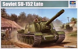
Upon first glancing at the box art for this kit, you might think that it looks rather odd - in fact, the artist has gotten the proportions a little wrong and the illustration looks more like an ISU-152 than an SU-152. Fortunately however, this discrepancy does not extend to the kit itself, where the superstructure and hull are correctly proportioned.
Built from the box, this kit represents an SU-152 manufactured after mid-August 1943, with dome-shaped ventilators on the roof of the superstructure and the later style exhausts with armored covers. The engineering of the kit however, makes it quite simple to back-date your model to represent a vehicle manufactured prior to mid-August 1943, simply by omitting parts or substituting them for other parts included in the kit.
The kit includes a new lower hull tub and hull sides, with sloped sides to correctly depict the 12 degree slope of the transmission compartment roof plate on the KV-1S hull, upon which the SU-152 was based. Dr Božidar Šarler has brought to my attention some discrepancies in the length of the hull. The sloped transmission compartment roof plate is some 5mm short compared to published drawings.
Since the shape of the upper hull sides immediately aft of the glacis was slightly different on the SU-152, the kit instructions direct you to cut away small portions at the upper front of the hull tub and the separate hull sides (parts WB1 and WB2). The parts are marked to indicate the sections to be cut away, and the surgery should not be beyond the skills of a competent modeler.
The instructions also direct you to open up two holes in the lower front hull, which will act as locating holes for the bracket that carried a pump to recharge the recoil/recuperator hydraulics. Check your references for the vehicle you intend to model however, since the position of this bracket varied somewhat. Some vehicles mounted it offset to the left as in the kit, while others carried it centrally on the lower front hull.
You must also open locating holes on the right-hand hull side (part WB2) for the ammunition reloading port and the small fender stowage box.
Assembly commences with the lower hull, adding the sides and lower rear hull plate (part WC8) to the lower hull tub. The base plates for the front and rear towing eyes depict the correct circular pattern seen on KV-1S hulls. The base plates for the rear towing eyes are molded integrally with the lower rear hull plate, while those for the front towing eyes are separate parts that are attached to the lower hull tub, which provides circular locating lines to indicate the correct positions.
The kit includes photo-etch parts for the exhaust air grille and deflector beneath the rear hull overhang. You must roll the deflector plate (part PE-A1) to the correct curvature before attaching the reinforcing plates (parts PE-A4). Alternatively, the kit includes a styrene part (WC28) which will look quite acceptable if the edges are thinned down with a file.
The kit includes the ammunition reloading port for the lower right-hand hull side (part WY6) along with the mounting bracket for the external loading tray (part WM19).
Step 2 adds the mounting bracket for the hydraulic pump, the glacis plate, the engine compartment and transmission compartment roof plates, and the left-hand suspension. The engine compartment roof plate (part WN11) is molded separately from the transmission compartment roof plate (part WC21). The hinges for the engine access hatch are integrally molded and are correctly positioned at the rear.
The mounting plates for the exhausts are also molded integrally with the roof plate and these are the square pattern used with earlier, unarmored exhausts, not the trapezoidal pattern used with the shortened, armored exhausts provided in the kit. If you wish to correctly depict the armored exhausts, you will need to carve away the mounting plates from part WN11 and replace them with styrene sheet, salvaging and reusing the bolt heads from the kit. If you wish to model a vehicle manufactured prior to mid-August 1943 however, you can leave the mounting plates as-is and use the earlier style exhausts (parts WC23 and WC24) which are included in the kit but marked as unused.
The transmission compartment maintenance hatches (parts WM3) are the late pattern with a raised lip around the circumference. These hatches are appropriate for an SU-152.
The radiator intake screens (parts WC22) depict the later pattern with the flattened forward section, and are also correct for the SU-152. The kit parts provide an adequate representation but like those in Trumpeter's earlier KV kits, they are molded solid. You may wish to replace them with aftermarket items. There are numerous alternatives but I have found that Eduard's TP089 set provides a good balance between detail and ease of assembly.
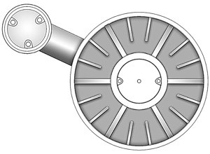
The suspension swing arms are the correct cast pattern, and the torsion bar hub caps include the correct three retaining bolts. Like all Trumpeter's KV kits however, the caps do not provide any positive location to correctly align the bolts with the swing arm. The drawing below shows the correct alignment. Note that the drawing shows the earlier reinforced steel road wheel, not the later pattern with lightening holes as seen on the KV-1S, SU-152 and KV-85. The alignment of the retaining bolts however, is the same.
Step 3 adds the return rollers, sprocket mounts and idler mounts to the left-hand side of the vehicle. No mention is made of the corresponding parts on the right-hand side but presumably you should add these too at this stage, since later steps show them in place. The return rollers are the correct all-steel type seen in photographs of the SU-152. When assembling the idler mounts, take care to fill the gap between the two halves of the mount (parts WA12 and WA13) since the mount was a single casting on the real vehicle.
The armored fillet on the glacis plate (part WY2) is also added at this stage. The part is missing the drain hole in the center at the lower edge, but this is easily added by carving a notch in the part with a sharp hobby knife.
The engine access hatch (part WM2) is the correct domed pattern and includes the inspection port for the overpressure relief valve molded integrally with the hatch. The hatch is a new molding in this kit and includes two integrally molded lifting rings in the lifting eyes on the forward corners of the hatch. These rings were commonly carried on SU-152s but if you wish, you can carefully carve away one or both rings for a little variety, since some photographs show the rings absent.
Step 4 constructs the road wheels and drive sprockets. The drive sprockets are the correct late pattern with eight retaining bolts for the convex hub. The road wheels are the all-steel type with eight lightening holes, commonly seen in photographs of SU-152s. The road wheels are supplied on a separate sprue which makes one wonder whether Trumpeter intend to release different road wheel patterns in subsequent KV-based kits.
Step 5 deals with the tracks. Trumpeter have departed from their earlier link-and-length tracks, in favor of individual link tracks. No vinyl tracks are included. The tracks depict the split-link tracks without a guide 'bump' on the split links, appropriate for an SU-152. However, the kit tracks scale out to 700mm wide, whereas all vehicles based on the KV-1S were fitted at the factory with 650mm tracks, except for a few early production examples with 608mm tracks. For accuracy, you should replace the tracks with aftermarket items. Numerous suitable sets are available including Friul ATL-54, Masterclub MC135028W, Miniarm B35018, Modelkasten SK-14 and Spade Ace SAT-35023.
Step 6 attaches the road wheels, sprockets and idlers. Note that you must attach the sprockets prior to attaching the mud scrapers (parts WC5 and WC6), or the sprockets will not fit. If you wish to leave the running gear separate for painting, wait until final assembly before you add the mud scrapers.
The exhausts are also attached at this stage. The kit provides the correct exhaust covers but the mounting plates are still the early type and will need to be fabricated from thin styrene sheet and after-market bolts. The drawing below shows the correct orientation of the mounting plates. Moskit also produces the correct exhausts in metal, though you will still need to fabricate the mounting plates.
The nose plate (part WC2) is also added at this stage. The kit part depicts the correct all-welded plate.
Step 7 adds the fenders and fender brackets. The fenders include the small front extensions commonly seen on SU-152s, and these are molded as separate parts. The fender brackets are supplied as photo-etch parts, though the kit also includes styrene parts for the vertical sections of the brackets (parts WA11 and WA14) if you prefer these. There is a problem with the brackets however, since they represent the brackets with an integral flange that was bolted vertically to the fender itself. While this is correct for most if not all KV-1S vehicles, the SU-152 was typically fitted with a different fender bracket where the flange was welded to the fender and then bolted horizontally to the bracket. For an accurate depiction of most vehicles, you will therefore need to make your own angled flanges from styrene or brass strip, and add your own bolts from aftermarket sources.
The kit includes the small fender stowage box for the number 8 fender position. Though molded as a single piece, the definition of the hinges and latches is very good.
The kit does not include the spare track links mounted on the number 9 and 10 fender positions, inboard of the external fuel tanks. These parts are not included in the kit, so you must source your own spare track links from the spares box.
Step 8 assembles the superstructure. The kit superstructure includes a row of rivets along the forward edge of the joint between the front and rear roof plates. These rivets were used to attach a flange to the underside of the front plate, upon which the forward edge of the rear plate rested and was bolted in place. This is appropriate for a late production vehicle. If you wish to depict an early production example from the spring or early summer of 1943, carefully remove these rivets (but leave the bolts along the rear edge of the joint). On early production vehicles, the flange was simply welded in place.
Note that the upper edge's of the kit's superstructure sides are beveled to match the angle of the roof plate. The superstructure sides on the Lubuskie museum's two vehicles have rough cut upper edges that are perpendicular to the sides, and not beveled to match the roof plate. This means that there are raised edges and cut-outs (usually roughly ground out) for the episcopes. This is shown in several photographs in KV - Technical History & Variants. However, there are a few wartime photographs that show the upper edges of the superstructure sides *without* the cut-outs (the easiest one to spot is on the rear side plate, right-hand side). This leads me to believe that on some vehicles at least, the plates *were* beveled to match the roof plate, or at least different in some other way that avoided the need to grind the cut-out into the upper edge for the episcope. Take a look here for some of these photos. I believe it is a matter of personal choice. If you want to model a vehicle with the rough-cut upper edges, then you can add strips of styrene to the upper edges of the kit parts and go to town with files and blades. If you want to model a vehicle with beveled upper edges, leave the kit parts as is.
Prior to attaching the ventilators (parts WY3) to the roof of the superstructure, you must open up two pairs of holes in the underside of the roof. The ventilators were first fitted in mid-August 1943 after combat experience at the Battle of Kursk. If you wish to depict a vehicle built before that time, omit the holes and the ventilators.
The kit provides two different types of pistol port for the rear plate; one with a flange (part WY8) and one without (part WN18). Check your references for the vehicle you are modeling.
Two gun barrels and muzzle brakes are provided for the 152mm ML-20S main armament, and Step 9 deals with assembling and attaching these. The kit provides a turned metal barrel with a single piece styrene muzzle brake, or a two-piece 'conventional' styrene barrel with the two halves of the muzzle brake molded integrally with the barrel halves. Unfortunately the muzzle brakes on both barrels are approximately 3mm too long, making the overall length incorrect. For accuracy, you should replace the barrels and muzzle brakes with aftermarket items. Aber, CMK, Eduard and RB Models all provide suitable barrels.
The large cast mantlet has some shape issues, since the angles of the front corners are far too sharp when compared to the real thing. The corners can be rounded off with a file or sanding stick to improve the contours, and then retextured with Mr Surfacer. The mantlet also omits the grab handle on the left-hand side, but this is easily added from thin brass wire.
The kit includes hand rails for the superstructure sides as well as the upper rear hull sides. These were seen on most if not all SU-152s but there were some variations in positioning so check your references for the vehicle you intend to model.
Step 10 covers the exterior stowage including the fender-mounted external tanks, pick axe and gun barrel cleaning rods. The mounting hardware for the tanks and tools is molded integrally with the parts, and you may wish to use aftermarket items for better detail. No update sets exist yet for this kit, but those will no doubt follow soon and in the meantime, you can source suitable parts from sets intended for the Eastern Express kits.
The kit includes copper wire for the tow cables with styrene parts to represent the steel ends. Steps 11 and 12 of the instructions deal with assembling and attaching the cables. Photographs show considerable variation in the method of stowage, so consult your references.
The kit provides a decal sheet with national insignia and markings, allowing you to make up your own markings to represent specific vehicles. If you want to represent a vehicle that the kit decals do not allow for, there are numerous aftermarket sources as noted in 1/35 scale Decals and Masks.
In summary, Trumpeter's SU-152 is not without its flaws, but with some care and attention it will build up into a very nice replica of the Zverboy. It will certainly require much less pain than the old Eastern Express kit.
